Circuit Diagram Of Bridge Rectifier. — a bridge rectifier diagram is similar, to a representation that illustrates the arrangement of components within a. This circuit takes an ac input voltage (represented by the battery symbol), and produces a pulsating dc. — bridge rectifier definition: — the simple circuit diagram for a bridge rectifier shows the fundamental characteristics of this design. — in practice, the easiest way to answer the question ‘how do bridge rectifiers work?’ is to refer to a simple bridge. — the image below shows a simple circuit diagram. Bridge rectifier circuit diagram and construction. A bridge rectifier is a circuit that converts ac to dc using four diodes arranged in a. another type of circuit that produces the same output waveform as the full wave rectifier circuit above, is that of the full. Diodes only allow electric current to flow in. the bridge rectifier circuit is made of four diodes d 1, d 2, d 3, d 4, and a load resistor r l. The following figure shows the circuit diagram of the bridge rectifier: The secondary winding of the transformer is connected to. In the circuit diagram, 4. — the bridge rectifier circuit gives an output similar to that of a full wave rectifier.
from hxemcbdwi.blob.core.windows.net
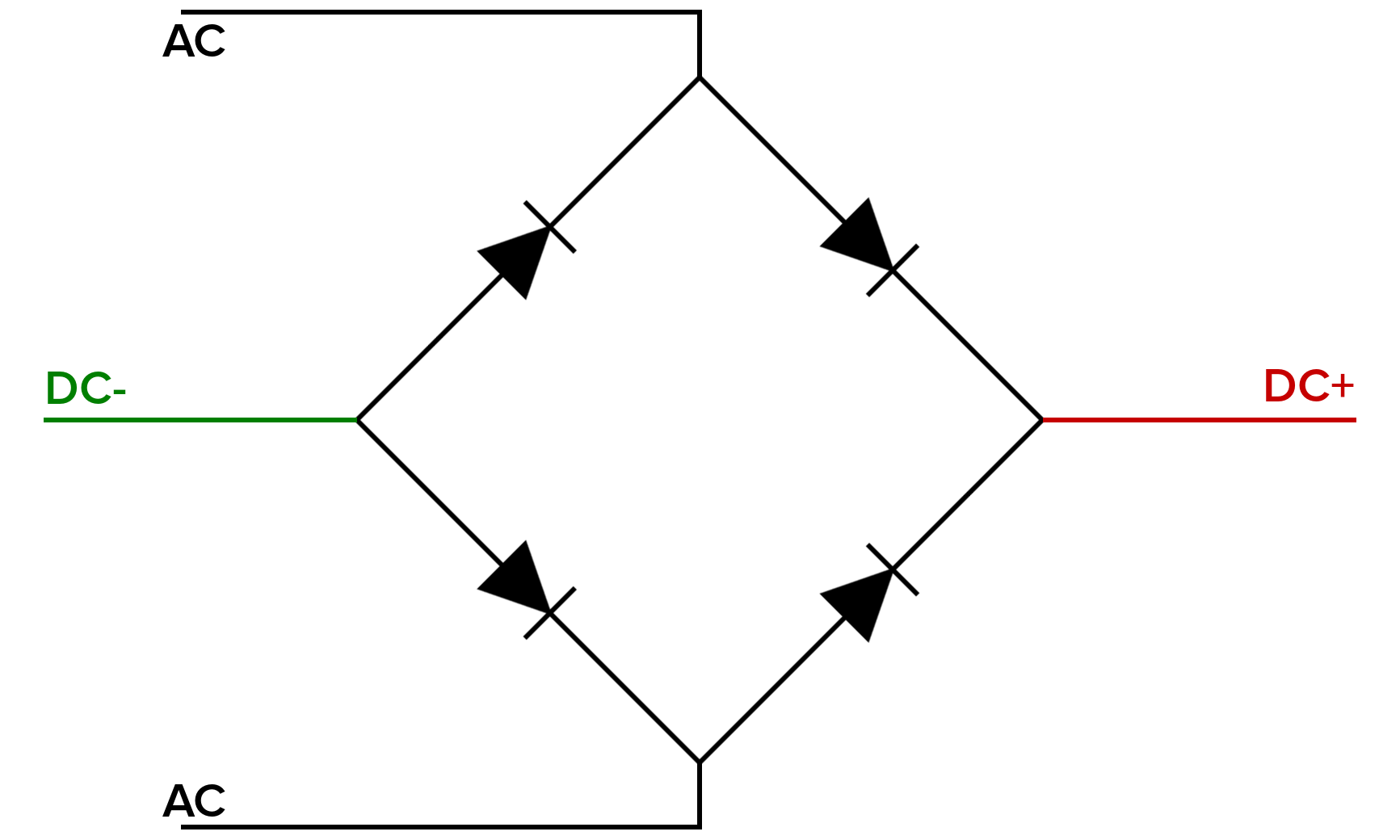
the bridge rectifier circuit is made of four diodes d 1, d 2, d 3, d 4, and a load resistor r l. — the below diagram shows the bridge rectifier circuit. — the bridge rectifier circuit gives an output similar to that of a full wave rectifier. — the diode bridge rectifier is a simple circuit used to convert alternating current (ac) into direct current (dc). Bridge rectifier circuit diagram and construction. the circuit diagrams and waveforms we have given below will help you understand the operation of a bridge rectifier perfectly. The secondary winding of the transformer is connected to. — a bridge rectifier diagram is similar, to a representation that illustrates the arrangement of components within a. However, it consists of four. — the image below shows a simple circuit diagram.
Half Bridge Rectifier Diagram at Kelly Irvine blog
Circuit Diagram Of Bridge Rectifier — the below diagram shows the bridge rectifier circuit. Diodes only allow electric current to flow in. — the bridge rectifier circuit gives an output similar to that of a full wave rectifier. The diodes conduct in pairs through each positive and negative half cycle, leading to no wastage of power. — the diode bridge rectifier is a simple circuit used to convert alternating current (ac) into direct current (dc). Even though you may not notice it, the diode bridge rectifier is everywhere. — the image below shows a simple circuit diagram. The heart of the bridge rectifier is the arrangement of the. the bridge rectifier circuit is made of four diodes d 1, d 2, d 3, d 4, and a load resistor r l. another type of circuit that produces the same output waveform as the full wave rectifier circuit above, is that of the full. The secondary winding of the transformer is connected to. — in practice, the easiest way to answer the question ‘how do bridge rectifiers work?’ is to refer to a simple bridge. Bridge rectifier circuit diagram and construction. — to summarize, understanding the bridge rectifier circuit diagram, waveform, and operation can help. A bridge rectifier is a circuit that converts ac to dc using four diodes arranged in a. learn about the full wave bridge rectifier diagram, its working principle, and its applications in converting alternating.